

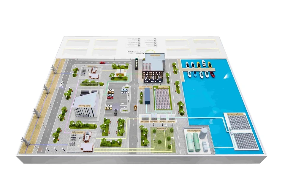


Custom Industrial Scale Model for an Integrated Energy Project in Oman
Industrial developments often involve several systems that are difficult to explain through drawings or equipment images alone. This custom industrial scale model was created for a project in Oman to present an integrated energy and infrastructure concept as one clear, physical display.
The model brings together green hydrogen facilities, wind turbines, floating and land-based solar panels, battery storage, substations, power transmission, a data center, commercial buildings and supporting transport infrastructure. Instead of showing these elements as separate products, the model explains how they belong to the same site and how energy, facilities and users are connected.
It is suitable for corporate showrooms, investment presentations, exhibitions, technical meetings and stakeholder briefings where the audience needs to understand both the overall development and the purpose of individual systems.


Project Overview
| Item | Project Details |
|---|---|
| Project type | Custom industrial scale model / energy infrastructure presentation model |
| Location | Oman |
| Main display content | Green hydrogen, wind power, floating solar panels, land-based solar arrays, battery storage, substations, power transmission, data center, commercial buildings, roads and marina facilities |
| Presentation features | Clearly divided functional zones, identification labels, color-coded system routes, site lighting and a transparent equipment display area |
| Typical materials | ABS, acrylic, resin, metal components, printed surfaces and electronic parts, selected according to each structure and equipment type |
| Lighting options | Constant lighting, sequential lighting or selected illuminated routes, depending on the presentation narrative |
| Control options | Single master control or separate zone controls can be specified |
| Base and protection | Custom display base; acrylic cover, modular construction and transport flight case available when required |
| Accepted reference files | CAD drawings, PDF plans, Revit or SketchUp files, STEP/IGES equipment files, renderings, photographs, brand guidelines and written equipment lists |
| Delivery support | Pre-shipment inspection, export packing, international delivery and on-site installation by agreement |
The exact scale, dimensions, materials, lighting logic and control method are confirmed for each project before production.
More Than a Miniature Site Plan
An industrial model should not simply reproduce every object at a smaller size. Its first job is to make a complex technical story understandable.
For this Oman project, the display needed to communicate a complete energy ecosystem. Green hydrogen production, renewable generation, energy storage, grid infrastructure, the data center and commercial facilities all had to remain visually distinct while still reading as one coordinated development.
To achieve this, the layout uses several levels of information:
Functional zones are separated by roads, landscape and clearly positioned labels.
Color-coded routes help viewers follow connections between energy generation, storage, distribution and consumption areas.
Large systems, such as the data center and substation, are given enough visual weight to remain recognizable from normal exhibition viewing distances.
Repetitive equipment, including photovoltaic modules and server cabinets, is simplified carefully without losing its technical identity.
Lighting helps establish focal points and keeps the model readable in a showroom or exhibition environment.
This balance between technical accuracy and visual clarity is an important part of our industrial model-making approach. A model can contain a large amount of detail and still fail if the audience cannot understand the system within the first few minutes.

Representing Different Energy and Infrastructure Systems
Green Hydrogen and Renewable Energy
The green hydrogen area includes storage vessels and supporting structures, while nearby wind turbines and solar arrays show the renewable generation side of the project. The equipment is simplified at scale, but key proportions, colors, symbols and arrangement are retained so that each technology can be identified quickly.
The solar section includes floating panels as well as land-based and rooftop installations. This allows the display to compare different application environments within one project rather than presenting solar power as a single generic component.
Substation and Power Distribution
Substations contain many narrow, repetitive and delicate components. Reproducing every real-world part at a small scale can make the display crowded or fragile. We therefore review the equipment hierarchy first and preserve the elements that define the facility: transformers, busbar structures, switchgear areas, boundary conditions and route connections.
For projects that require a stronger technical explanation, selected equipment can be enlarged, made removable or presented as a separate detail model.
Data Center and Transparent Equipment Display
The data center uses a partially transparent presentation area so the internal equipment arrangement can be viewed without removing the building from the site. This method is useful when the relationship between the external architecture and internal technical equipment is part of the presentation.
Transparent walls, removable roofs, cutaway sections or exploded assemblies can be selected depending on the audience. A client presentation may require a clean and simple view, while an engineering or product demonstration may need more internal detail.
Supporting Architecture and Transport
Commercial buildings, roads, parking, vehicles, landscaping and marina facilities provide the operational context around the energy systems. These elements are not treated as decoration only. They help explain scale, access, circulation and how the industrial facilities connect with the wider development.
Our Approach to Industrial Model Making
Glory Models has nearly 20 years of model-making experience across architectural, industrial, engineering and exhibition projects. This combination gives us a useful perspective: we understand both the precision required for technical equipment and the visual organization needed for a large presentation model.
Our work on an industrial scale model normally begins with three questions:
What must the audience understand first?
Which equipment and routes must be technically identifiable?
Which details can be simplified without changing the meaning of the project?
The answers determine the scale, level of detail, material selection, lighting sequence, labels and viewing angles. This prevents the project from becoming a collection of accurate but disconnected miniature objects.
Drawing Review and Technical Confirmation
Industrial model inputs often come from several departments. The site plan may be supplied by an architect, equipment files by an engineering team, color standards by marketing and the presentation sequence by an exhibition contractor. These files may not use the same revision, coordinate system or level of detail.
Before fabrication, our team consolidates the information into a model production package. The review normally covers:
overall site boundary and model orientation;
equipment list, quantities and installation positions;
building elevations and visible internal areas;
pipe, cable or energy-flow routes that need to be shown;
corporate colors, logos and equipment labels;
lighting zones, sequence and switch logic;
removable parts, transparent sections and maintenance access;
model dimensions, base height, transport restrictions and final installation route.
A 3D layout or marked-up drawing is provided for approval where required. Production begins after the main geometry, colors, labels, lighting logic and display direction have been confirmed.


Materials and Fabrication Strategy
Different parts of an industrial model require different production methods. For a project of this type, we normally combine:
CNC and laser-cut ABS or acrylic for buildings, platforms, roads and repeated structural parts;
3D printing for tanks, turbines, vehicles and equipment with complex geometry;
clear acrylic for water surfaces, transparent enclosures and cutaway displays;
printed or engraved textures for photovoltaic modules, paving and technical labels;
metal or reinforced components where thin parts require additional strength;
hand assembly, painting and finishing for equipment differentiation and brand color matching.
Material selection is based on the required appearance, minimum part thickness, transport conditions and expected display period. Fragile details are reviewed before production so that they can be strengthened, made replaceable or packed separately when necessary.
Lighting, Interaction and Presentation Logic
Lighting should explain the project rather than simply make the model brighter. Depending on the presentation purpose, the model can include:
constant lighting for buildings, roads and landscape;
sequential LEDs to represent power, data, water or material flow;
individual zone controls for specific systems;
push-button, touchscreen or programmed presentation modes;
synchronized labels or a digital screen for guided demonstrations.
During technical confirmation, we define what each illuminated route represents, its direction, color and operating mode. A single master switch may be suitable for a permanent showroom display, while separate controls are more useful for guided presentations.
Production, Inspection and Approval
The model is checked at several stages rather than only after assembly. Typical checkpoints include the base layout, major equipment positioning, color samples, lighting tests and final completion.
Before shipment, we provide photographs and videos for review and test:
overall dimensions and orientation;
equipment quantities and identification;
labels, logos and color consistency;
lighting functions and control logic;
removable parts and access panels;
surface finish, cleaning and final assembly;
compatibility of the model, base, acrylic cover and packing case.
Any agreed adjustments are completed before the model is packed.


Packing, Delivery and Installation
Transport planning starts during model design, particularly for large exhibition or showroom projects. If the completed model cannot safely pass through elevators, doors or exhibition access routes, it may be divided into modules with concealed joints and numbered electrical connectors.
Depending on the project, the delivery package can include a protective acrylic cover, custom foam supports, a reusable flight case, handling instructions and an installation guide. For overseas projects, we can coordinate international delivery and arrange on-site assembly or installation where required.
Maintenance and After-Sales Support
Industrial display models are often used for several years and may travel between exhibitions. Where maintenance access is required, the base can be designed with removable panels so lighting controllers, wiring and power supplies can be inspected without disturbing the display surface.
We can also provide circuit identification, operating instructions, spare vulnerable parts and remote troubleshooting support. Maintenance requirements should be discussed before production so access and replacement methods can be built into the model rather than added later.
Why Choose Glory Models?
Industrial and Architectural Experience in One Team
This project combines equipment, buildings, landscape, transportation and energy infrastructure. Our experience in both architectural and industrial models allows these different elements to be produced as one consistent display rather than as separate visual styles.
Decisions Based on the Presentation Purpose
We do not automatically copy every detail from the source files. We first identify the audience, viewing distance and technical message, then recommend the scale, detail level and interaction method that support that purpose.
Coordinated In-House Production
Equipment parts, architectural structures, landscape, lighting assembly and display bases are coordinated by our own production team. This shortens communication between disciplines and makes it easier to control revisions during fabrication.
Clear Approval Points
Layout, equipment positions, colors, labels and lighting logic are confirmed before final assembly. Clients receive progress updates and can review defined checkpoints instead of waiting until the entire model is complete.
Designed for Overseas Delivery
Model dimensions, modular joints, electrical connectors and packaging are considered together. This is particularly important for projects delivered to the Middle East, Australia, Europe and North America, where the model may need to arrive ready for a fixed exhibition or opening date.


Frequently Asked Questions
1. What files are required to quote an industrial scale model?
A site plan, equipment list, target model size, delivery location and required completion date are usually enough for an initial review. CAD, Revit, SketchUp, STEP or IGES files can be added for a more accurate technical assessment. Reference images are also useful when formal drawings are incomplete.
2. How do you determine the correct scale?
We compare the available display area with the smallest equipment that must remain recognizable. For an integrated energy site, the overall footprint and the detail required for substations, tanks, server cabinets or solar panels must be considered together. If one system cannot be shown clearly at the main scale, we may recommend an enlarged detail model or removable section.
3. Can the model demonstrate energy or material flow?
Yes. LED routes can show electricity, data, water, gas or material movement. Before production, the client confirms the route, direction, color, sequence and whether the effect should run continuously or only during a guided presentation.
4. How is technical accuracy checked?
We prepare a consolidated equipment and layout review based on the latest approved files. Key equipment positions, quantities, labels, brand colors and system routes are confirmed before fabrication. Progress images and functional test videos are supplied before shipment.
5. Can equipment be removable or shown internally?
Yes. Depending on scale and purpose, equipment can be detachable, enlarged, sectioned or placed behind transparent panels. Removable roofs and cutaway structures are useful for data centers, factories, substations, storage systems and process equipment.
6. How long does production take?
A detailed schedule is issued after the drawings, model size, lighting and interaction requirements have been reviewed. As a general reference, design and 3D confirmation often require about one week, followed by approximately four to six weeks of fabrication after approval. Complex interactive or large modular models may require more time.
7. Can the model be delivered to Oman or other Middle Eastern countries?
Yes. We can prepare export packaging, coordinate international transport and support on-site installation where required. The delivery method is selected according to model dimensions, exhibition date, destination and whether a reusable flight case is needed.
8. What maintenance should be planned for a permanent showroom model?
For long-term display, we recommend a dust cover, stable indoor temperature, access to electrical components and periodic surface cleaning. If the model includes lighting or programmed effects, maintenance access and spare electronic parts should be defined before production.
Request a Project Review
If you are planning an industrial, energy, infrastructure or technology display, send us your available drawings, required model size, delivery location and target date. Our team will review the information and recommend a suitable scale, level of detail, presentation method, packing solution and production schedule.
Contact Glory Models to discuss your industrial scale model project.
Hot Tags: industrial scale model, China industrial scale model manufacturers, suppliers, factory, Battery Energy Storage System Models, Machinery and Equipment Models, models of plant layout, museum model ships, Plant Layout Models, truck plant and machinery model world


